
What is Epoxy Captivation
In RF and microwave system design, selecting the right panel-mount coaxial connector involves a critical structural decision: Should you specify standard Mechanical Captivation or Epoxy Captivation?
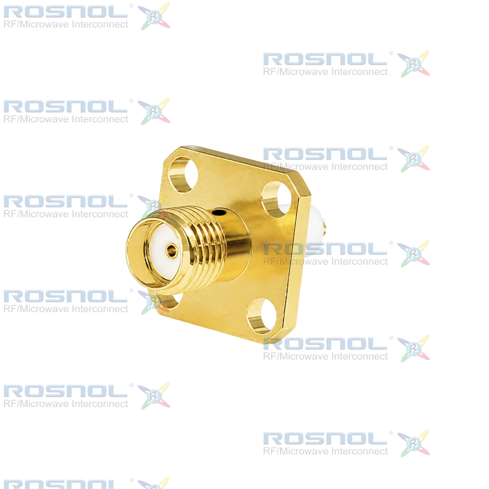
Comparing the datasheets of the two ROSNOL SMA Female (Jack) 4-Hole Flange Mount Connectors—both featuring passivated stainless steel bodies, gold-plated beryllium copper center contacts, 50 Ω impedance, DC to 18 GHz frequency range, VSWR ≤ 1.30, and stub solder terminals—their external dimensions and electrical specifications are virtually identical:
Mechanical Captivation Version: Part Number SMA2GFA50-1320A/9X
Epoxy Captivation Version: Part Number SMA2GFA50-1320A-EC/9X
Interestingly, under the "Mechanical Data" section of both datasheets, the minimum retention thresholds appear identical (Axial Captivation ≥ 27 N; Radial Captivation ≥ 3 Ncm). However, from an RF engineering perspective, the underlying physical structures, long-term reliability, and ideal operating environments for these two designs differ significantly. Below is an engineering breakdown of how they compare and when to use each.
1. Structural Principles: Mechanical vs. Epoxy Captivation
Inside an SMA connector, the dielectric insulator is made of PTFE (Teflon) due to its low dielectric constant and high-temperature resistance. However, PTFE has two inherent physical limitations: an extremely low coefficient of friction and a Coefficient of Thermal Expansion (CTE) roughly 10 times higher than that of metal. Under sustained mechanical or thermal stress, PTFE is also prone to "cold flow" (creep).
Mechanical Captivation — SMA2GFA50-1320A/9X
How It Works: This design uses zero adhesives. Instead, precision machining creates barbs, grooves, or steps on the center contact and PTFE insulator. It relies on an interference fit (press-fit) and the natural elasticity of PTFE to lock the center contact into the insulator and secure the insulator inside the stainless steel housing.
Engineering Characteristics: Clean, adhesive-free construction with no risk of chemical outgassing. While cost-effective and straightforward to manufacture, its positional stability during soldering or thermal cycling depends entirely on the physical rigidity of the PTFE.
Epoxy Captivation — SMA2GFA50-1320A-EC/9X
How It Works: As shown in the engineering drawing for SMA2GFA50-1320A-EC/9X, a small injection port (labeled Epoxy Captived) is drilled into the side of the body between the coupling threads and the flange. During assembly, a specialized electronic-grade, two-part epoxy is injected through this port to fill micro-anchoring grooves across the outer body, PTFE insulator, and center contact.
Engineering Characteristics: Once cured, the thermoset epoxy forms a rigid structural bond that locks the metal housing, dielectric, and center pin into a single unified assembly, completely eliminating the risk of PTFE slippage.
2. Five Key Engineering Differences in Real-World Applications
While both versions pass the ≥ 27 N axial pull test at room temperature, their performance diverges during production assembly and long-term field deployment:
1. Resistance to Pin Recession During High-Temperature Soldering (Critical Difference)
Both models feature a 0.3 mm diameter, 3.2 mm long Stub Terminal designed for direct soldering onto PCB microstrip traces or internal RF module substrates.
- Without EC (SMA2GFA50-1320A/9X): During hand soldering or reflow, heat conducts rapidly from the beryllium copper center pin into the surrounding PTFE. As PTFE heats up, it expands and softens, drastically reducing the grip of its mechanical barbs. Even slight pressure from a soldering iron or fixture can cause the center pin to recess, protrude, or tilt.
- With EC (SMA2GFA50-1320A-EC/9X): Thermoset epoxy does not soften or melt under soldering temperatures. It holds the center contact rigidly in place, ensuring the critical mating interface reference plane remains exact before and after soldering.
2. Phase Stability and VSWR Consistency at 18 GHz
At 18 GHz, the wavelength in free space is only about 16.6 mm, making the transmission line highly sensitive to microscopic dimensional shifts.
- Without EC: Over hundreds of mating cycles or prolonged vibration, micro-creep in the PTFE can allow slight center pin recession. This alters the air gap at the mating interface, causing irreversible drift in Return Loss and VSWR (specified at ≤ 1.30) as well as phase instability at upper frequencies.
- With EC: Rigid locking maintains the exact axial geometry of the center contact, delivering superior impedance matching, phase stability, and measurement repeatability all the way up to 18 GHz.
3. Endurance Under Extreme Thermal Shock
Both connectors are rated for an operating temperature range of -65°C to +165°C and comply with MIL-STD-202 thermal shock standards.
- Without EC: At -65°C, PTFE contracts much more than the surrounding stainless steel housing. Over repeated thermal shock cycles, this differential contraction can create microscopic stress-relief gaps at the press-fit interface, gradually loosening the center contact.
- With EC: The cured epoxy bridges dimensional tolerances and absorbs thermal stress, effectively counteracting CTE mismatches between metal and dielectric components.
4. Outgassing Performance in High-Vacuum Environments
- Without EC: Constructed purely of stainless steel, beryllium copper, and virgin PTFE, this version contains zero organic polymers or adhesives. In ultra-high vacuum (UHV) environments—such as space satellite payloads or vacuum test chambers—there is zero risk of adhesive outgassing contaminating sensitive optical or RF components.
- With EC: Although electronic-grade low-outgassing epoxy is used, strict aerospace or UHV protocols often favor adhesive-free mechanical designs unless the specific epoxy formulation holds space-flight qualification.
5. Unit Cost and Lead-Time Flexibility
- Without EC: Assembled via automated machining and press-fitting, resulting in fewer manufacturing steps, higher throughput, lower unit cost, and shorter lead times.
- With EC: Requires additional dispensing, vacuum degassing, thermal curing, and cosmetic inspection steps (to ensure no epoxy overflow around the injection port), resulting in a slightly higher unit price.
3. Application Selection Guide: When to Use Each Model
Specifying Epoxy Captivation for every application can lead to unnecessary BOM costs. Below is a practical guide on when to deploy each model:
When to Choose SMA2GFA50-1320A-EC/9X (Epoxy Captivation)
- High-Frequency (12 GHz to 18 GHz) & Phase-Sensitive Systems: Ideal for phased-array radars, high-frequency transceivers, and microwave assemblies where exact reference planes and phase stability are mandatory.
- Demanding Soldering Processes: Essential when soldering stub terminals directly to PCB pads using manual soldering irons, high thermal profiles, or setups lacking precision pin-support fixtures.
- High-Vibration, High-Shock, & Harsh Thermal Environments: Recommended for automotive radar, ruggedized outdoor base stations, aerospace/defense avionics, and heavy industrial sensors.
- High-Mating-Frequency Test Fixtures & Lab Equipment: While rated for 500 mating cycles, test-bench panels frequently experience off-axis torque and heavy handling by multiple operators. The -EC version prevents accidental center pin push-back during frequent connections.
When to Choose SMA2GFA50-1320A/9X (Mechanical Captivation)
- Low-to-Mid Frequency Applications (DC to 6 GHz / 8 GHz): For Wi-Fi 6/7, Sub-6 GHz 5G infrastructure, and general IoT modules, micron-level axial tolerances have negligible impact on VSWR, making mechanical captivation completely sufficient.
- Controlled Indoor & Static Environments: Well-suited for data center servers, indoor telecom gateways, and stationary test racks not exposed to severe vibration or thermal shock.
- Ultra-High Vacuum (UHV) Chambers: The preferred choice for internal vacuum chamber interconnects where eliminating any potential source of organic outgassing is a top priority.
- High-Volume, Cost-Sensitive Production: Once automated soldering fixtures are validated to prevent axial stress during assembly, SMA2GFA50-1320A/9X offers substantial cost savings for high-volume manufacturing without sacrificing electrical performance.